(1)
.
In this lab, you will gain some experience using two basic electronic instruments: a DC power supply, which produces an adjustable DC voltage, and a digital multimeter, which can measure resistance and voltage. You will construct some simple circuits using resistors and light bulbs and make measurements to check the validity of Kirchhoff's Rules.
Let us review some of the fundamentals of electric circuits. The resistance
R of a circuit element is defined as the ratio of the voltage drop across
the element to the current flowing through it,
(1) ![]()
.
If the resistor is ohmic, then the ratio V/I is a constant, independent of current or voltage, and the resistance is constant. However, many materials, such as light bulb filaments, are non-ohmic; their resistance depends on the applied current and voltage. When a light bulb filament is glowing white hot, its resistance is much greater than when it is cool.
Resistors can be combined in series or in parallel. The total resistance of several resistors in series is just the sum of the individual resistances. Note that the total series resistance is always larger than any of the individual resistances.
![]()
(2) ![]() (series)
(series)
The total resistance of several resistors in parallel is always smaller than any of the individual resistances according to the formula:
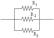
(3) ![]() (parallel)
(parallel)
In the case of two resistors in parallel, equation (3) becomes:
(4) ![]() (parallel).
(parallel).
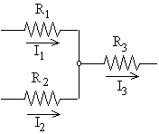 Kirchhoff's
junction rule states that, in steady state, the sum of the currents
flowing into a junction must be equal to the total current flowing out
of the junction (otherwise charge would be building up at the junction,
and we would not be in steady state.) In the example shown here, there
are two currents I1 and I2 shown flowing into a junction
and one current I3 is coming out. The junction rule says that
 ![]() .
.
Kirchhoff's loop rule states that, in traversing any closed loop in a circuit, the sum of the voltage rises must equal the sum of the voltage drops. You can think of voltage as a kind of electrical pressure. Voltage differences push charges through an electrical conductor, just as pressure differences push water through a pipe. Water in a pipe always flows from regions of high pressure to regions of low pressure, except in a pump, which forces the water to flow toward high pressure. Likewise in a circuit, (positive) charges flow from high voltage to low voltage, except within a battery or power supply, which forces the charges "upstream" toward higher voltage. The voltage at a point in an electrical circuit, like the pressure at a point in a network of pipes, has a constant, well-defined value. If we traverse any closed loop in a circuit, or in a network of pipes, we must return to our original voltage (or pressure). Thus the total voltage(pressure) drop must just equal the total voltage (pressure) rise.
 The two instruments
you will use in this lab are a DC power supply and a digital multimeter.
The DC power supply produces a constant voltage, which can be adjusted
from between zero and 30 volts with the voltage knob on the front panel.
The power supply has three output terminals: plus (red), minus (black),
and ground (green). The ground terminal is always at zero volts. In this
experiment, the ground and minus terminals are tied together by a metal
connector so the minus terminal is also at zero volts. Both the current
and voltage produced by the power supply can be read on meters on the front
panel. Also on the front panel is a current-limit knob, which can be adjusted
to limit the maximum output current, to prevent damage to sensitive circuit
elements. In this lab, the current knob has been set and clamped in place
so the power supply cannot produce more than about 0.6A current.
The hand-held digital multimeter (DMM) is a wonderful little device which can be used to measure voltage and current (DC or AC), resistance, and capacitance. In this lab, we will use it to measure resistance and DC voltage only. When making any measurement, there are always 2 wires to the DMM. One of the two wires always goes to the COM (common) terminal. To measure voltage or resistance, the second wire is attached to the VW input. In this lab, all our measurements will be DC, so the DC/AC switch (upper right) should always be in the DC position. The DMM has an alarm; it sings if you have wires plugged into positions which conflict with the central knobís position. (For instance, if you have the wires in COM and VW , but have the center knob in the "Amps" quadrant.)
The DMM has two special cables called "needle probes" - long wires with pointed metal ends. You can quickly measure the voltage between any two points in a circuit by touching the points with the needle probes.
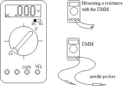 When measuring a resistance
with a DMM, you must disconnect the source of the resistance (be it single
resistor or some combination of resistors) from any other devices, such
as power supplies. Never try to measure the resistance of a resistor while
it is in a circuit.
 Procedure
Part I. Measurement of resistance
Each position should have 5 resistors: one 15W , one 40W , one 1500W , and two 3000W resistors. These values for the resistances are given by the manufacturer and are approximate. Each resistor is mounted in a double-banana plug connector. Begin by carefully measuring the resistance of each resistor with your DMM and record your measured resistances. The double-banana mount can be plugged directly into the DMM, without using any wires.
There are also two light bulbs at each position. Use the DMM with the needle probes to measure the resistance of each light bulb filament. Remember to always record your measurements directly in your lab book in ink.
Take the three large-valued resistors (the 1500W and the two 3000W resistors) and place all three in parallel, by stacking the double-banana plugs as shown in the diagram. Now use the DMM to measure the total resistance of this parallel combination of three resistors. Compare your measured Rtotal with the value you expect from your earlier measurement of the individual resistances and equation(3).
Repeat this procedure for some other combination of resistors in parallel and some other combination of resistors in series.
Use the DMM with needle probes to measure the resistance of your body between your right and left hands. Measure the resistance by holding the probes tightly with dry hands. Then wet your fingers and repeat the measurement. You will find that wet skin has a much lower resistance than dry skin. (Stabbing each hand with a probe would result in an even smaller resistance, but this procedure is not recommended.)
Part 2. The resistance of a hot light bulb filament.
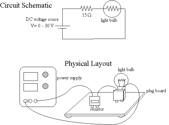 Using connecting wires
and the "plug board", build a circuit consisting of the DC power supply
in series with the15W resistor and one light
bulb. Whenever you build any circuit with a variable voltage source, you
should always make certain that the voltage is turned down to zero (fully
CCW) before connecting any wires.
Slowly, turn up the voltage until the bulb begins to glow brightly (not too bright, we want the bulbs to last!). Now using the DMM with needle probes, measure the voltage V across the power supply terminals, the voltage VR across the 15W resistor and the voltage VB across the light bulb. Using the known resistance of the resistor (measured in Part I), compute the current IR, though the resistor. The current though the light bulb IB is equal to IR, since the resistor and bulb are in series. From these measurements, you can compute RB, the resistance of the bulb. Compare with the value you measured in Part I. Why are they different?
![]()
Part 3. Qualitative investigation of circuit behavior.
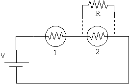 Construct the
circuit shown below, consisting of two light bulbs in series with the power
supply. (The resistor R will be added later). Slowly increase the voltage
until the bulbs are glowing (not too bright!). Now place the R = 40W
resistor in parallel with bulb 2 as shown. What happens to the brightness
of the two bulbs? Explain.
Repeat this procedure with R = 1500W and
R = 15W . What happens in each case? Explain.
Part 4. Kirchhoff's Laws.
Construct the following circuit (Remember to keep the voltage turned down to zero, initially!). Increase the power supply voltage to about 10V. Now measure the voltage across the power supply terminals and across each resistor. From your measured voltages and the resistances you measured in Part 1, compute the current through each resistor. Use your measured voltages and computed currents to verify Kirchhoff's loop rule and current rule.

Prelab questions. (Due at the beginning of your lab session, as usual.)