
Light is a wave, an electromagnetic wave, and under the proper circumstances, it exhibits wave phenomena, such as constructive and destructive interference. The wavelength of visible light is roughly 600 nm = 0.0006 mm, and this wavelength l sets the scale for the appearance of wave-like effects. For instance, if a broad beam of light partly passes through a wide slit, a slit which is very large compared to l , then the wave effects are negligible, the light acts like a ray, and the slit casts a geometrical shadow. However, if the slit is small enough, then the wave properties of light become apparent and a diffraction pattern is seen projected onto a screen illuminated by the light from the narrow slit.

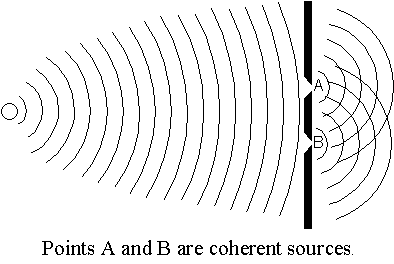 We now ponder
the light from two coherent light sources a distance d apart. Coherent
sources emit light waves that are in phase, or in sync. If we think
of light like a water wave, we can imagine that two coherent sources each
emit an identical succession of wave crests and troughs, with both emitting
crests at the same time. One way to create such coherent sources is to
illuminate a pair of narrow slits with a distant light source.
Consider the light rays from the two coherent point sources made from
infinitesimal
slits
a distance d apart (diagram below). We assume that the sources are emitting
monochromatic (single wavelength) light of wavelength l
. The rays are emitted in all forward directions, but let us concentrate
on only the rays that are emitted in a direction q
toward a distant screen (q measured from the
normal to the screen, diagram below) . One of these rays has further to
travel to reach the screen, and the path difference is given by ![]() .
If this path difference is exactly one wavelength l
(or any integer number of wavelengths), then the two waves arrive at the
screen in phase and there is constructive interference, resulting in a
bright area on the screen. If the path difference is
.
If this path difference is exactly one wavelength l
(or any integer number of wavelengths), then the two waves arrive at the
screen in phase and there is constructive interference, resulting in a
bright area on the screen. If the path difference is ![]() etc., then there is destructive interference, resulting in a dark area
on the screen.
etc., then there is destructive interference, resulting in a dark area
on the screen.
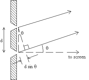

If q is small, then ![]() and maxima occur on the screen at
and maxima occur on the screen at ![]() ;
minima occur at
;
minima occur at ![]() .
.
A complete analysis (not show here) yields a pattern of intensity vs.
angle that looks like:

As shown below, the angle q (measured from
the center of the screen) is related to the distance x measured on the
screen by ![]() , where L is the distance from the screen to the source of light (the aperture).
, where L is the distance from the screen to the source of light (the aperture).

If the angle q is small (less than a few degrees), then to an excellent approximation,
![]() and so
the locations of the interference maxima are given by
and so
the locations of the interference maxima are given by ![]() .
.
The uniform 2-slit interference pattern shown above is seldom observed
in practice, because real slits always have finite width (not an infinitesimal
width). We now ask: what is the intensity pattern from a single slit of
finite width D? Huygens’ Principle states that the light coming
from an aperture is the same as the light that would come from a collection
of coherent point sources filling the space of the aperture. To see what
pattern the entire array produces, consider first just two of these imaginary
sources: one at the edge of the slit and one in the center. These two sources
are separated by a distance D/2.
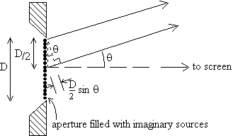
The path difference for the rays from these two sources, going to the
screen at an angle q , is ![]() ,
and these rays will interfere destructively if
,
and these rays will interfere destructively if ![]() .
But the same can be said for every pair of sources separated by D/2. Consequently,
the rays from all the sources filling the aperture cancel in pairs, producing
zero intensity on the screen when
.
But the same can be said for every pair of sources separated by D/2. Consequently,
the rays from all the sources filling the aperture cancel in pairs, producing
zero intensity on the screen when ![]() or, if q is small,
or, if q is small, ![]() .
(First minimum in single slit pattern.)
.
(First minimum in single slit pattern.)
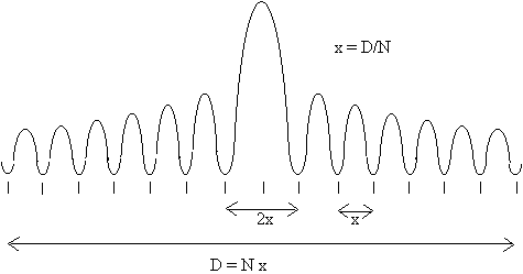
A complete analysis (too complicated to show here) yields an intensity pattern, called a diffraction pattern, on the screen that looks like...
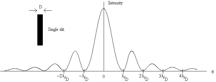
[The central maximum is actually much higher than shown here. It was reduced by a factor of 6, for clarity.] The single slit diffraction pattern has minima at
![]() (Minima
of single slit pattern.)
(Minima
of single slit pattern.)
So the separation of minima is l /D, except
for the first minima on either side of the central maximum, which are separated
by 2l /D. If x is the distance on the screen
between minima, then ![]() .
.
When the aperture consists of two finite slits, each of width
D, separated by a distance d, then the intensity pattern is a combination
of both the single-slit pattern and the double slit pattern: the amplitude
of the two slit interference pattern is modulated by a single slit diffraction
pattern: 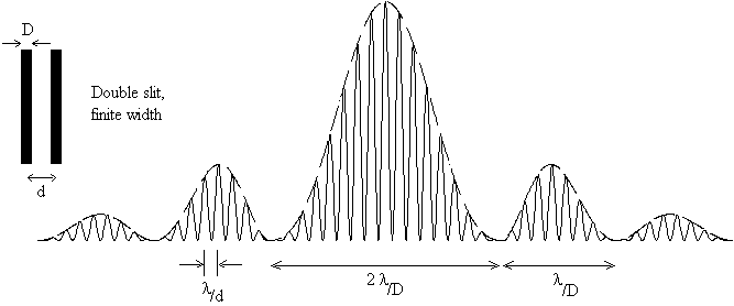
In this full pattern, the finely spaced interference maxima are spaced ![]() apart, while the more widely spaced minima of the single-slit diffraction
pattern are separated by
apart, while the more widely spaced minima of the single-slit diffraction
pattern are separated by ![]() or
or ![]() . Note
that an interference maximum can be wiped out if it coincides with a diffraction
minimum.
. Note
that an interference maximum can be wiped out if it coincides with a diffraction
minimum.
An aperture consisting of many slits of uniform width and spacing is
called a diffraction grating. Using exactly the same arguments as
above, one can show that a diffraction grating, whose slit separation is
d, produces maxima with a separation of ![]() ,
the same as a double slit, except the maxima from a grating are very cleanly
separated and sharply peaked. The more slits in the grating, the more sharply
peaked the maxima.
,
the same as a double slit, except the maxima from a grating are very cleanly
separated and sharply peaked. The more slits in the grating, the more sharply
peaked the maxima.
The resolution of an optical instrument such as a camera, a telescope
or the human eye is defined as the smallest angle which the instrument
can resolve. Diffraction effects limit the resolution of any optical instrument
to ![]() , where
l
is the wavelength of the light used, and D is the diameter of the main
light-gathering optical element (the objective lens of a telescope, the
pupil of the human eye, etc.). Many texts use the formula
, where
l
is the wavelength of the light used, and D is the diameter of the main
light-gathering optical element (the objective lens of a telescope, the
pupil of the human eye, etc.). Many texts use the formula ![]() ,
called the Rayleigh criterion, but the minimum angle of resolution q
is difficult to measure precisely, and in practice the factor 1.22 is not
experimentally significant.
,
called the Rayleigh criterion, but the minimum angle of resolution q
is difficult to measure precisely, and in practice the factor 1.22 is not
experimentally significant.
Experiment
The light source in parts 1 and 2 of this experiment is a He-Ne laser
which produces a monochromatic beam with a wavelength of l
= 632.8 nm and a beam diameter of about ![]() .
The power output of our lasers is about 1 mW, a small amount, but still
enough to damage your retina if you look directly into the beam.
.
The power output of our lasers is about 1 mW, a small amount, but still
enough to damage your retina if you look directly into the beam.
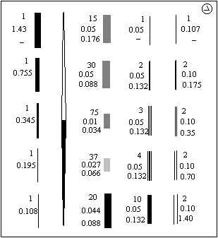

The aperture consists of an opaque photographic negative, containing
several single, double, and multiple slits. The arrangement of slits on
the plate is shown here. The numbers are those given by the manufacturer
and are not always accurate. (This particular plate is often
called a Cornell Plate, since apertures of this kind where first used at
Cornell University.)
Place the Cornell plate in its holder and mount it on the optical bench
a few centimeters in front of the laser. Place a piece of white paper in
the clipboard and place it at the far end of the bench.. Then shine the
laser through the various apertures and observe the diffraction patterns.
Spend a few minutes exploring. Note the appearance of the single, double,
and multiple slit patterns. In particular, observe how the single slit
pattern changes as you vary the width of the slit.

This diagram shows the relation between the width s of some feature
(any feature) on the screen, the angular width q
of that feature, and the distance L from the aperture to the screen.
Part 1. Single Slits
In this part we will test the relation ![]() ,
where x is the separation of minima on the screen in the single slit diffraction
pattern. Measure the distance L from the slit to the screen. Observe the
diffraction pattern on your paper screen for each of the three smallest
single slits (the three with approximate widths D = 0.10, 0.20, 0.35 mm).
With a pencil, mark the positions of as many of the minima that you can
see and measure the spacing x between adjacent minima on the screen, for
each of the three slits. To do this most accurately, measure the width
of the entire pattern and divide by the number of maxima in the pattern
(central max counts as two!). From your measurements, using the wavelength
l
=632.8 nm, compute the slit width D for each of the three slits and compare
with the manufacturer's widths.
,
where x is the separation of minima on the screen in the single slit diffraction
pattern. Measure the distance L from the slit to the screen. Observe the
diffraction pattern on your paper screen for each of the three smallest
single slits (the three with approximate widths D = 0.10, 0.20, 0.35 mm).
With a pencil, mark the positions of as many of the minima that you can
see and measure the spacing x between adjacent minima on the screen, for
each of the three slits. To do this most accurately, measure the width
of the entire pattern and divide by the number of maxima in the pattern
(central max counts as two!). From your measurements, using the wavelength
l
=632.8 nm, compute the slit width D for each of the three slits and compare
with the manufacturer's widths.
Part 2. Double Slit
Repeat the above procedure with the one double slit aperture
which has a nominal slit separation of 0.35 mm (the one in the middle of
the right most column on the Cornell plate). Using the wavelength l
=632.8 nm, and make measurements of the diffraction pattern which allow
you to compute d, the separation of the slits. Compare your value for d
with the manufacturer's.
Part 3. Resolving power of the human eye
In this part, you will measure the resolving power of your eyes to see how close your vision is to "perfect", that is, diffraction-limited performance.
First, measure the diameter D of the pupil of your eye (under normal room-light conditions). With one eye open, look closely at the image of your pupil in a mirror and measure your pupil's diameter with a clear plastic ruler placed on the mirror or over your eye.
Next, measure the angular resolution of your eye with the following procedure: One of your partners will stand on a "zero position" mark on the floor some distance away and will hold up an eye-test chart for you to view with both eyes open. The test chart consists of an array of vertical bars and an array of horizontal bars, as shown below. Beyond a certain distance, the human eye cannot resolve the bars and the arrays appear to be gray blotches rather than black stripes on a white background.
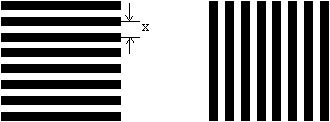
Begin by standing so far from your partner that the chart cannot possibly
be resolved, and then signal your partner to hold up the test chart. The
chart is held up with either the vertical bars or the horizontal bars to
your right, but you will not know which orientation is used. Slowly, approach
your partner and when you believe you can resolve the bars, indicate with
hand signals which side of the chart has the horizontal bars. Repeat this
test several times, varying your distance somewhat. Each time you "read"
the chart, your partner should give the thumbs-up(correct) or thumbs-down(incorrect)
signal and then you should turn away briefly while your partner randomly
rearranges the chart for the next test. Find the maximum distance L (marked
on the floor) at which you can consistently read the chart correctly. The
center-to-center separation x of the bars is marked on the chart. The angle
q
which you can resolve is then q = x/L. Report
this angle in radians, degrees, and in arcminutes (60 arcminutes = 1 degree).
Compare this angle with the theoretical diffraction-limited resolution
of q = l /D. Use
l
= 550 nm (the middle of the visible spectrum) in your calculations. Also
report the results of your partners' eye tests. How close is your vision
and your partners' to "perfect"?
Prelab questions (due at the beginning of the lab period)
 A He-Ne laser
(wavelength
l = 633 nm) shines through a double
slit of unknown separation d onto a screen 1.50 m away from the slit. The
distance on the screen between the m=4 maxima on either side of the central
maximum of the two-slit diffraction pattern is measured and is found to
be 3.4 cm. What is the separation d of the two slits?
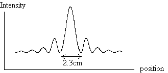 A He-Ne laser
(wavelength
l = 633 nm) shines through a single
slit of unknown width D onto a screen 1.50 m away from the slit. The distance
on the screen between the m=1 minima on either side of the central maximum
of the diffraction pattern is measured and is found to be 2.3cm. What is
the width D of the slit?