Physics 2140 - Lecture
notes on Resonance
(From lecture on Mon, 10/30)
See also the short version
of this class day
Consider a linear R-L-C circuit. We have shown earlier that the
impedence Z = R + i w L + 1/(i w C) = R + i (wL - 1/wC)
(I will use w and
 interchangeably, to represent the angular frequency of the input voltage)
(Recall that impedence simply gives the ratio of voltage to current, V=I Z,
when voltages, currents, and charges are expressed in "complex space". At the
end of the day, the physical voltage, current, and charge is obtained by taking
the real part)
Note the sign of the imaginary part of Z. if wL = 1/wC, i.e. if
 ,
then the impedence is purely real. It's as though the L and C weren't even
there!
Now, since V = IZ, and everything in that equation is complex, you can solve
for I, take the absolute value, and note that the absolute value of a complex
quantity is also the maximum that the real part can ever be. Since we
often have circuits where the voltage is input (and so doesn't vary, except for
its sinusoidal time dependence), it is the current which adjusts itself. And,
since we have a linear circuit, the current is constant through all the
elements, but the voltage across individual elements varies. So, if we want to
know the power being consumed in an element, the relevent formula comes
from
P = I^2 R, i.e. the power is proportional to the square of the current.
In our case, with linear R-L-C, we have that the power consumed in the resistor
is

(I get the denominator above from Z = R + i (wL-1/wC))
Since (wL-1/wC)^2 is positive definite, the denominator is at its
smallest when w^2=1/LC, (any other frequency, smaller or larger, will
make the denominator bigger) which means the power consumed in any circuit
element is at its largest there. This point is called resonance.
Imagine driving this RLC circuit with different frequency voltage sources. (Fix
V0, so the current will adjust itself every time) I can slightly rewrite the
above expression, by doing a little algebra, to get

The response (power, energy consumption) is biggest when the denominator is
smallest, i.e. when w is resonant,
 .
.
If R is small, then gamma is small (<< w0). In this case,
convince yourself that for most any frequency, the 1/gamma^2
term in the denominator makes that whole piece huge, and so the power is small.
(Put another way, if R -> 0, power -> 0) This limit is subtle, convince
yourself that it's true. The argument breaks down when we're on resonance,
because then power is just V^2/R, and in fact gets BIG!
This is the idea behind a radio circuit. Make an RLC circuit, pick R small. The
antenna will pick up all frequencies, and feed them into the circuit. But, out
of all the different frequencies being fed in, the only one that puts any power
into the resistor (the speaker) is the one that's right on resonance. So, you
select out of all the continuum of frequencies, only one (or a tiny range)
which gets "amplified" and produces power. As you change the dial, you might be
simply changing the capacitance C, which doesn't do much except change what the
resonant frequency is!
What happens mathematically when you are close to resonance, but not right on
it? Then part of the denominator of the power becomes

On resonance, this is 1, as before. But NEAR resonance, in particular, when
 ,
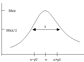
then this term becomes 2, i.e. the power is half as big. So this means that as
frequency shifts by gamma/2, the power drops by two. This yields the full width
at half max, or FWHM. (In this case, the full width arises by going off by
gamma/2 either below or above, so the full width is gamma)

This curve is called a Lorentzian, and is characteristic of many resonances.
An example in mechanics:
A particle on a spring in 1-dimension, with friction and a driving force which
is sinusoidal, feels three forces;
F=-kx (the spring force),
F=-dv (a drag force, opposite the direction of motion, i.e. friction),
and
 ,
the sinusoidal driver with amplitude F0 and frequency w.
So Newton's law says

This looks rather like our circuit equation (sort of), which was
 .
(The inductor acts like inertia, the resistor acts like drag, and the capacitor
plays the role of the spring.)
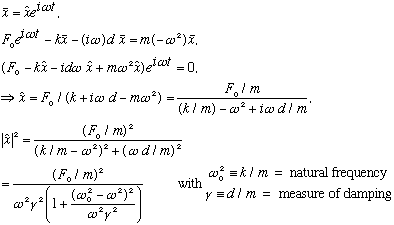
Solve this just like we did the RLC circuit in the first place. i.e. introduce
a fictitious solution,
 ,
which is complex (and in the end, we will only use
 !) We get:

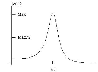
This formula is almost exactly what I had before for power, except for a
factor of (omega)^2 in the denominator, which slightly changes the appearance
of the plot near zero frequency. (The reason the formula is slightly different
is that, in circuit analogy, the above is the square of the charge, not
the current!) Near the peak, that factor doesn't change things significantly.
So again, we have a resonant system. If you drive it with a frequency near the
resonant frequency, the system produces large amplitude motion. Driving at any
other frequency results in very little motion. At zero frequency, this function
goes to (check!) (F0/k)^2, which in fact makes sense. At zero frequency, it's
just a static push on a spring, and F0=kx!

See also the short version
of this class day
Here is the
Next lecture
Back to the list of lectures
 interchangeably, to represent the angular frequency of the input voltage)
(Recall that impedence simply gives the ratio of voltage to current, V=I Z,
when voltages, currents, and charges are expressed in "complex space". At the
end of the day, the physical voltage, current, and charge is obtained by taking
the real part)
 ,
then the impedence is purely real. It's as though the L and C weren't even
there!

 .
.
 ,
then this term becomes 2, i.e. the power is half as big. So this means that as
frequency shifts by gamma/2, the power drops by two. This yields the full width
at half max, or FWHM. (In this case, the full width arises by going off by
gamma/2 either below or above, so the full width is gamma)
 ,
the sinusoidal driver with amplitude F0 and frequency w.
 .
(The inductor acts like inertia, the resistor acts like drag, and the capacitor
plays the role of the spring.)
 ,
which is complex (and in the end, we will only use
 !) We get:
