
Please send us your questions. (Put Phys1120 in the subject line of your email!) They may be about anything - this week's homework assignment, course content, course administration, or whatever. If appropriate, we will email an answer to you directly. Or, in many cases (where we think the question might be of general interest), we will instead post an anonymized version of the q+a on this page instead. (we'll chop your name off the posting). Please email us your questions at Steven.Pollock@colorado.edu or Victor.Gurarie@colorado.edu.
Error in posted concept test solutions:
Prof. Pollock, On page 30 of the concept tests for chapter 26 (w/ answers) it says the answer is B but I'm getting A. This is because I figured the distance between point p and +2Q to be sqrt((1/2)*s^2), which simplifies to (1/sqrt(2))*s. When you plug this into coulomb's law (E=kQ/d^2) you have to square d, which comes out to be (1/2)*s^2, which ultimately yields answer A (there shouldn't be sqrt(2) anywhere in the final formula). I've triple checked this result before writing this email to make sure I'm not making any mistakes, so either I've made the same mistake 3 times or there's a typo. I want to be sure!
Yup, you're absolutely right. Looks like everything in the concept test solution was right, except the letter of the answer itself. Nice detective work!
Video:
Prof. Pollock - just happened upon this video and thought you'd enjoy it. Here's the link:
http://gizmodo.com/gadgets/science/tesla-coils-playing-the-mario-bros-theme-are-unsurprisingly-awesome-319384.php
Comic:
I found this comic to be very entertaining and thought you might like to see it. Be sure to read the alt-text if you read it.
Cool article:
Professor Pollock: Very interesting article on NIST and the atomic clock that is located there. Briefly discusses electromagnetic waves that we have learned and also general relativity.
http://www.wired.com/science/discoveries/news/2007/12/time_nist?currentPage=1
Small typo in lecture notes:
Hi Steve,
In your notes on inductors, 32-7.gif, you say that the potential energy of a solenoid = (1/2mu0)B*Volume. Shouldn't it read B^2? (judging from the derivation as well as our text book)
Yup! Good eye!
Same student notices another funny thing in the lecture notes:
Your chapter 35-33 notes say that V(t)=V0sin(2pift). The book, however, says instantaneous emf=emf0*cos(omega*t), where omega=2pif. How can both of these be possible, or which one is correct?
Are you worrying about the fact that I use a sin, and the book uses a cos? It's really ok (or you could say we're BOTH wrong :-), the most general formula should be
V(t) = V0 sin(2 pi f t + phi), where "phi" is ANY arbitrary, constant added inside the sin function. It's a "phase shift".
(If phi=0, this fomula gives V0sin(omega t), but if phi=pi/2, you get V0sin(omega t + pi/2) = V0cos(omega t)!
A sin function and a cos function are almost the SAME function, except the cos is "shifted left" by a quarter of a wave. (So that sin starts off heading up, but cos starts off at its max, when the argument is 0).
I'm usually pretty casual about whether I call something sin or cos, in situations like this. Another way to look at it is that both the book and I are right, we are simply disagreeing on when we want to call t=0. I start MY clock when the voltage passes through a zero. The book starts ITS clock when the voltage passes through a maximum. But "when you start your clock" isn't really a fundamental physics issue, it's just a small detail.
Hope this helps! Let me know if you're still confused at all. Glad you're looking closely at these things, this is great.
Steve
CAPA 15 format question (#1):
I hate to bother you with a trivial capa query, but on the first question the instructions are confusing. Should I enter the answer in the form "G,L,E" or "T,F"? How can I enter it in "T,F" if the dots haven't been replaced with "G,L,E" answers yet?
Thanks for your time!
No problem - here's my CAPA question (yours will be slightly different)
The transverse displacement of a streched string from equilibrium as a function of time and position is given by:
y=0.13cos(3x-54t). x and y are in m; t is in s.
(Select T-True, F-False, G-Greater than, L-Less than, E-Equal to, If the first is T and the rest F, enter TFFF). (Note: dots (....) must be replaced by G, L, or E!)
A) The speed of the wave is ..... 18 m/s
B) The wavelength is ..... 1 m
C) The period is ..... 0.1 s
D) The wave travels in the positive x direction
Since A, B, C have dots ("....") in them, those must be filled in with a G,L, or E. But since D is just a statement, that needs to be a T or F. So in my case, if I thought that the speed of the wave is greater than 18 m/s, but I thought the wavelength is equal to 1 m, and the period is equal to 0.1 sec, and I did NOT think the wave travels in the positive x direction, I would fill in
GEEF
(No spaces, no commas, just those 4 letters).
So the ellipsis ( "....") in a problem is supposed to represent a blank where you fill in G, L, or E (meaning >, < or =), but if there is no ellipsis, it is merely a statement, which is either true or false.
Does that make sense? Sorry if it's confusing, I guess we haven't done one in this format before! Let me know if you're still puzzling about it.
Photons and EM Waves:
Dear Prof. Pollock,
I was curious about Einstein’s work with photons and how it relates to Maxwell’s equation. I understand that light travels in waves and that electromagnetic forces cause us to see light but where does the whole thing about photons fit in?
In 1800, Young did an experiment which very conclusively showed that light is a wave. (He observed that light interferes with itself, like waves do, whereas particles do NOT! I can tell you more about interference if you don't know about it) So by the time Maxwell came around, like 50-60 years later, the idea that light was a wave was VERY well established. But nobody knew what was "waving", that's really what Maxwell helped us figure out - it was the E and B fields! For the next 40 years, all was well - light is simply an electromagnetic wave, the math was simple, physicists got pretty cocky! Then things began to get a little confusing, and evidence started piling up that, in many circumstances, light also behaves like a particle after all! But it was strange, because in *some* respects it's unambiguously a wave, and in other respects it's unambiguously like a stream of particles.
Anyway, bottom line is that Einstein (and Planck, and Bohr, and others) realized that in many ways light really does seem to come in little bundles, little chunks, called photons. A photon is LIKE a "particle of light". It travels in a straight line, can be absorbed and emitted, carries a small but certain amount of energy. So sometimes we think of light as coming in photons ( generally when dealing with atomic-scale systems). And sometimes we think of light as traveling like waves (generally when dealing with larger systems, macroscopic systems, like radio antennas or cell phones or microwave ovens,...)
(Ironically, it turns out that Isaac Newton had originally thought of light as a stream of particles - I think he called them 'corpuscles'? - old Isaac was a smart cookie! The modern view of photons is much more nuanced, Newton really didn't have it all right, but it's cool that his ideas, albeit modified, stand the test of time. Newton fought with Huygens, who thought that light was a wave. In those days, the 1600's, it was pretty hard to prove one way or the other, because the wavelength of light is so small, it was just experimentally difficult to *distinguish* between waves or streama of particles!) )
If you take Phys 2130 or Phys 2170, you'll learn all about this! By the way, although early quantum theory began to help sort all this out, modern QED (quantum electrodynamics) has really pulled the whole story together. (But it's still very hard to *visualize*!) QED is basically the theory which takes Maxwell's equations, combines them with the rules of quantum mechanics, and makes sure everything is completely consistent with Einstein's theory of relativity. It's a neat bundle. Maxwell's equations are still "true", although more in an average or large-scale sense. When you get down inside of individual atoms, QED tells you how things need to get properly fixed up. (But I'm afraid you don't really study QED in detail in physics classes till you get to grad school, we don't really cover it, except qualitatively, at the undergrad level. )
Steve
Dental X-rays and Physicists X-rays:
Prof. Pollock, How do heavy duty x-ray sources work, like the one at the Brookhaven National Laboratory on Long Island? Unfortunately I visited Brookhaven this summer without having this physics class first! Following is my speculation regarding the matter from both my memory and the little tid-bits I've picked up from our lecture.
From my memory: they shot electrons into a tunnel/tube/thing where they encountered a bunch of magnets that caused them to wiggle (makes sense: charge moving in a B-field experiences a force...it seems conceivable that they could arrange magnets in such a way to make the electrons wiggle).
From what I've picked up in lecture so far: wiggling charges create changing E-fields, creating B-fields, which are apparently EM-waves, which is light, which are x-rays.
Is this the basic idea of how you get x-rays from electrons? Is this perhaps how these "x-ray sources" work?
Thanks!
Yup, pretty much exactly right! We'll be talking about this more tomorrow in lecture. There are a variety of ways to get X-rays, the *old* way was to accelerate electrons and then smash them into some solid material, precipitously stopping them. The massive acceleration (deceleration?) of the electron is also a kind of "wiggle", and creates an EM wave. It's just a little uncontrolled, contains many frequencies, and goes every which way. But this is still fundamentally how the X-rays at, say, the dentist's office are made. The technical word for this "braking radiation" is from the German word for brake - ( Brem) and radiation, or "strahlung", hence the lovely word Bremmstrahlung.
The controlled wiggles at Brookhaven are just a more sophisticated way of doing this (and by choosing the wiggle frequency, you can get more "pure" X-rays of a well-defined frequency, rather than a mishmash.
Steve
Bose-Einstein Condensates (from the picture of the week, about a month ago)
Professor, I was wondering with the Bose-Einstein condensation mentioned earlier how all the atoms group together in one form. Does this mean that as you approach zero kelvin that you would also be approaching an imaginary time axis because it appears that you begin to lose all of your boundary conditions as the matter is being cooled towards zero. Thank you,
The Bose-Einstein condensate is a quantum-mechanical effect, in which atoms can all go into a common "state". There are two kinds of particles in the world - bosons and fermions. Bosons are allowed to live in the same state, fermions are forbidden from going into the same state. (A common example of the latter is the statement you may have learned in Chemistry, that "no two electrons can be in the same state in an atom" (which is why as you add more and more electrons, they fill up higher and higher energy states, or orbitals) Electrons are fermions, so they can't "pile up" in this quantum mechanical sense. Bosons are different, they CAN all go into the same state. An example is a laser, in which the "particles" involved (the photons!) are all in the same quantum state - every photon in the laser has the same properties, same energies, same locations, same phase... So the bose-Einstein condensate is really rather like a laser, except instead of a bunch of photons all going into the same state, here it was a million atoms all going into the same state, basically sitting at the bottom of a magnetic "bottle".
Check out the Physics 2000 site for some cartoon-like explanations of the physics. It's aimed at high school students, but it's pretty fun. http://www.colorado.edu/physics/2000/bec/
Steve
Inconvenience:
Professor Pollock, I've never actually seen the Inconvenient Truth, but I've been hearing the rumor that it says that unplugging things that you aren't using saves energy. I'm trying to wrap my brain around this because if the switch isn't on and nothing is happening, it seems to me like this is a broken circuit and no current will flow. I'm all for saving energy but I really want to know if this is a useful thing to do or if it is just nonsense?
thanks a lot!
Good question - I think it depends on the item! Unplugging a lamp which is already off won't save any energy at all, your logic is indeed quite sound. However, many electronic devices nowadays do consume power when they are nominally off. My TV, for example, when "off" is still consuming a small amount of power. (This way, when I use the remote to turn it on, it is "listening" for the remote, and turns on very quickly. If I have unplugged it and then plug it back in, it has a much longer warmup period). TVs and stereos and microwaves, etc. also have clocks and other simple electronics that stay on, and e.g. sometimes memory that needs small amounts of power. Also, anything with a transformer in it (typically down-converting voltage to charge batteries or maintain memory or simply work with electronics that can't handle wall voltage) is likely to continuously convert a small amount of electrical energy into heating, which is pure loss, and goes on all the time, even when there is no obvious load. The typical power consumption of such devices when they appear "off" is generally a few watts. Not a lot (compared to when they are on, when they will consume more like 50-150 W) but I think it's the sheer number of such things that makes it an issue - if you have a half dozen or dozen of these things, and everyone else does too, it does add up. When I leave my computer in my office, it goes to sleep (which means the monitor turns off, and the hard drive shuts down), but again it is consuming a few watts continuously if I don't truly power it down. (With my *laptop* it seems worse - the thing does feel warm to the touch even when it's been closed for hours. So I definitely unplug it when I'm not using it.)
A quick web search on your question took me here:
http://www.aceee.org/consumerguide/electronics.htm
They have a nice chart of typical power consumption in "off" or "standby" modes. Most electronic devices seem to be chewing 1-10 W even when they appear "off". Bear in mind that a constant 4 Watt power drain * 24 hrs/day* 365 days/year = 35 kW*Hr burned in a year. That costs you a piddling $3 (for the year!) for that one item. For comparison, I use about 250 kW*hrs (electric) every *month* (total), and that's considered about 1/4 the US national average for a household. So we're not talking a lot here, but it's not zero either. And then, if you have a half dozen such items, and so does everyone in America, suddenly you're talking 35 kW*hr /yr/item * 6 items/house * 100 million households = 20 billion kW hrs consumed annually. That's the total annual energy production of TEN power plants the size of Boulder's Valmont station, so indeed it's not zero.
But the bottom line tends to be one of convenience (hence Al Gore's title :-) . Unplugging some items (like the fridge) is obviously a terrible idea. Unplugging a TV can be a pain if you like the "instant on" feature (and especially if it means having to reprogram the clock and stuff!) Most of the items in my house that are small power drains are indeed just inconvenient to get to (I'm thinking e.g. of the wireless hub, which goes through a minute long reboot process if you unplug it, or the microwave which has a clock, or ... etc.... ) I could totally unplug those when I go to work, I guess. I wish they had an "off" button and a "really off" button, that could go a long way!
By the way, I kind of think Inconvenient Truth may be worth watching some time. The problem I have with it is that it is aimed so completely at the "general public" that it waters down a lot of issues, sensationalizes others, tries to get people *emotionally* vested (rather than rationally vested, which is what I would prefer). I guess it makes sense to take this approach if you want to communicate important ideas and drive people to take action, but sometimes it feels like propaganda. And of course Gore mixed in some politics with the environmental and scientific issues, which I find unfortunate, there was no need to do so and it unnecessarily alienates a lot of people. Still, I think you know enough science to be able to recognize the elements that are manipulative (and therefore not be so manipulated!) while still absorbing the good ideas in it - there is also a lot of compelling information mixed in there. Of course, you can learn it all on your own without having to watch the movie, and I'd say it's worth informing yourself. Issues of energy and the environment will likely more and more dominate the political, economic, and social landscape for the rest of our lives, it's good to keep informed!
See you in class, - hope you had a great break!
Steve
Fluorescent Bulbs:
hi professor,
i was recently discussing making the switch over to all florescent bulbs in our house with my mom, and she said she tried them in places where we have dimmer switches in place, and they dont dim like incandescents. I tried it myself, and i could tell that they dim very slightly, but not much at all. do you have any insight as to why they don't really respond to dimmer switches? I assume the switches are like a variable resistor that changes the voltage in the circuit, am i correct? Why do the florescents not respond to the drop in voltage like the incandescent bulbs do?
thanks a lot
First of all, it's a great thing to switch out the bulbs in your house - it can add up to a LOT of energy savings. Although those bulbs are a lot pricier at the store, do the calculation yourself, estimate how much money you save over the lifetime of the bulb, and you'll discover they more than pay for themselves (many times over, in fact!) I first did that calculation in 2000, checked it because I couldn't believe it, then went and switched out almost all the lights in my house. No regrets, definitely a good call. Many of those bulbs are still going, by they way, they can live a long time! But now to your question, because indeed you can't use those bulbs everywhere.
Incandescent bulbs are responding directly to the V^2/R heating, so if you change the voltage (which is indeed what the dimmer switch does) you continuously vary the power in the bulb, and thus the brightness. But Fluorescent bulbs work totally differently. There is an electronic "ballast" which up-converts the voltage (much like a transformer), and this final voltage needs to be high enough to get voltages that ionize the gas in the bulb. It's more of an "on or off" kind of thing, if you turn down the voltage, you basically don't get the gas to glow at all, or not nearly as effectively. The ballast is basically designed for 120 V, so if you put it on a dimmer switch not only does the bulb not work as well, but it can shorten the bulb life considerably (if the ballast gets fried, the bulb won't work). I think there are special compact fluorescent bulbs specially designed to work on such switches, but they're more expensive. I'd saythe best thing to do is either go back to the old bulbs for those outlets, splurge on the pricey CF's (just for those outlets), or just swap out the dimmer switch for a regular one - it's not a difficult chore (but use some common sense, be sure to turn off the breaker switch to that room before unscrewing wires!) Good luck! (By the way, the other place you can't use them is outside - again unless you buy specially designed bulbs. There is usually more moisture (esp on bad weather days) which can mess with the ballast. Too bad, because that's one place a lot of people tend to leave a light on all night long!)
Steve
Interesting Particle Physics in the news...
Hi Professor,
I thought you would find this interesting so I decided to pass it
along to you. I can't understand 90% of his actual paper on the
theory, and I'm not sure if you can either! But the article is pretty
interesting, and after the new Super Collider is running we shall see
if he is right...
Have a nice day!
Fluffy Newspaper Article: http://www.telegraph.co.uk/earth/main.jhtml?xml=/earth/2007/11/14/scisurf114.xml&CMP=ILC-mostviewedbox
The physics article: http://arxiv.org/abs/0711.0770v1
Interesting, but I'm not at all sure what to make of it (And no, I must confess I can't understand a lot of his paper either, despite a pretty good background in theoretical particle physics! I get the gist, but not the details) Interestingly, in my PhD thesis from 1988 I presented calculations of possible limits that a precise experiment on parity violating electron scattering from protons would produce, for an E8xE8 superstring model (which was in style at the time) So the invocation of the E8 group is not something entirely new in particle physics!
Have a great break,
Steve
Question about magnetic field directions:
hi prof pollock
i was just reviewing for the exam and i had a question about the stop to think #32.4 (p. 1011) i understand why the current is clockwise, but why is the north pole on the bottom? i always thought that b fields flow from north to south. thanks a lot in advance for clearing this up
We had a concept test like this in class, and if you look at the posted solutions, my figure may help you understand it. I agree it's a little confusing.
Field lines go from north to south OUTSIDE of a bar magnet (!) but of course they form continuous loops (by Ampere's law), which means they have to go the "wrong way" INSIDE the magnet. So, you need to picture this as a very thin magnet, and see those field lines as all being "outside" - Imagine that you were to hold that ring in your hand. It would look like a flat magnet to you, right? And, you would see the field lines are emanating OUT the bottom, and that means you would say you are holding a magnet with the north pole facing down, yes? (Because field lines emanate OUT from the north pole!)
Alternatively, if you hold another bar magnet (like a compass) near that ring, the other magnet will "line up" with the field lines. Which means that if, say, you hold the other magnet above that ring, the compass will point along the field lines towards the top of the ring. That means the NORTH end of the compass is pointing towards the TOP of the ring, which makes the top of the ring the south pole of the ring (right? The north end of a compass is attracted to the south end of other magnets, opposites attract!)
Looks like no matter how I think about it, I keep getting that the north pole is at the bottom, in agreement with the text...
Does this all help? Let me know if it's still confusing!
Cheers,
Steve
Question about AC power:
Professor Pollock: I 've been wondering about fluorescent lights -- if they are flickering 120 times a second, and they're going from 'all the way off' to 'all the way on', why do we perceive them as 'all the way on' all the time? Wouldn't it be just as likely that we'd see them as all the way dark? Or -- when they are lit for that fraction of a second, are they twice as bright as we perceive them, so our brains mix together the bright and dark flickers so they seem constantly half as bright as they actually are?
Just wondering
Good question. I'm not sure of the answer, I can imagine one of two things - perhaps (as you suggested) we just "integrate" and then perceive the average power (which is half the max). Or perhaps we have persistence of image, and so perceive full power and our brains basically ignore the periods when we're receiving no signal. Most likely of all is that it's something even more complicated and interesting :-)
I'll do a simple demo in class at some point soon where I swing a (special, fairly robust) fluorescent bulb in a big circle. You'll be able to "see" the flickering then, because it will be on at certain positions on the circle, and off at others, so you'll see a sort of "dashed line" instead of a continuous streak.
See you in class! Steve
Centripetal and centrifugal force, and magnetic fields.
Professor, I was reading over the "Magnetic Field" lecture notes from the webpage and noticed that, in the part about forces on moving charges in magnetic fields, it says: "This force does not speed up the proton, it is a centripetal force!"
If I recall correctly, when learning about Uniform Circular Motion in Physics 1110, we learned that there was really no such thing as a "centripetal force." We said that such forces should actually be called "centrifugal forces."
Has everything I've ever known just gone down the drain? Or are there really centripetal AND centrifugal forces, and what's the difference?
Gosh, hopefully everything you know has not gone down the drain, that would be a royal mess!
"Centripetal" means "center-seeking". In an inertial reference frame (which is what we always use in Phys 1110 and 1120!) Newton's laws hold. Any object moving around a circle MUST feel a force that keeps it going in a circle (otherwise it will, of course, just go in a straight line, as Newton's first law would demand!) Now, what force would make an object go in a circle? You would have to have a force that pushes it towards the CENTER of the circle at all points. (Can you visualize that? Just take ONE step tangent to the circle, and ask "which way would a force be *needed* to make me move in a circular path?) That's centripetal. Think of the moon orbiting the earth. Why doesn't it just "run away"? Because the earth PULLS it, towards us. At all times in its orbit, the moon feels a steady pull towards planet earth, a centripetal force. Any object which goes in a circle needs such a centripetal pull.
What about that other word (centrifugal) which I *never* use when teaching 1110 :-) Well, centrifugal means "outward". This is sometimes referred to as a "fictitious force". It is a force perceived in a non-inertial reference frame (and thus, a force felt in a frame where Newton's laws do not hold in the usual ways!) That's why we avoid such reference frames like the plague in Phys 1110 - it's ok to work in a non-inertial frame (sitting at my desk, I live atop a rotatating ball, and that's not an inertial frame!) but it's more complicated, and you need to introduce "fictitious" forces to allow you to properly do mechanics with Newton's laws. So e.g, when you're in the passenger seat of a car, and the driver makes a hard left turn, what do you feel? It *feels* like you are "thrown outwards" (to the right, against the door). That would be called a centrifugal force. But you invoke it because YOU are sitting inside the accelerating reference frame of the car. It's a fictitious force, there is NOTHING "real" which actually pushes you outwards! What does an observer OUTSIDE the car see, e.g. how does Isaac Newton (from his perch in heaven :-) observe this event? He sees you going in a straight line, and then suddenly the CAR starts turning left underneath you, but you keep going straight (to satisfy his first law) so what happens? You go straight, the car turns left under your seat, and suddenly you are colliding with the right door. The right door is PUSHING YOU LEFT. That's what keeps you in the car, and makes YOU start to go left too (along with the car). The true force on you is the force *of* the door *on* you, which is to the left (towards the center of the circle your car and you is going in, a centripetal force!) But your *perception* was that a magical force "threw you outwards" against the door. That would be the centrifugal force, which is purely imaginary, just a way of trying to make sense of things inside this funny non-inertial frame.
Is this making sense? So bottom line. When you observe from any inertial frame (i.e. if you are "at rest") and watch particles move in circles, there must be a true, physical force which pushes those particles in towards the center of the circle (a centripetal force) to make them go in uniform circular motion. Gravity is the physical force for planets going in circles, the magnetic field creates the physical force for protons running in circles in a cyclotron...
It's possible that your memory/vocabulary from 1110 has gotten exactly reversed? Happy to chat more if this is still confusing (but I'm guessing at this point it's more about semantics, and memory, than anything?) Find your notes from 1110 if you want, that might help you!
Hope this is all making sense - keep asking if it doesn't!
Cheers,
Steve
Inductive cooking:
Hi Professor, So my cooktop broke last weekend, and I am looking through the internet for replacements. I find three basic approaches to cooking are available: Gas, Electric, and Induction. The first two are readily explainable and I am familliar with, but the third is entirely new to me. I read further, and find out that a: induction cooktops require using special "feromagnetic" cookware, and b: that induction cooktops actually do not heat up anything but the pot. So after a bit of head scratching I decided that you would be the right guy to ask. How does this induction cooking work? Sounds like a phys1120 issue involving magnets and electricity. I have some ideas, but I was wondering if you are at all familliar with this. They are terribly pricey, by the way, but twice as efficient as gas (according to Best buy)
Thanks,
We will talk about induction in class - starting that topic basically tomorrow! Inductive stoves are very interesting - the idea of is that if you change a magnetic field (in the stovetop) over time, you induce local electric fields by Faraday's law (and thus, if there is a conductor present, electric *currents* inside!). So, if you create a B field right close to the stovetop, a conducting piece of cookware just above it will have induced electric currents swirling around in it, and if the metal is resistive, those currents will produce power (I^2R) , thus heating the metal. So the COOKWARE gets hot, but the STOVE is not - it's literally "cool" - you could put your HAND there and nothing would happen (because the conductivity of your body is too low to produce any significant currents, so no heating of the hand!) People with kids especially like these things, for obvious reasons. (Of course, the pot itself gets hot, which is what then heats the food - so you can still burn yourself, but not e.g. after you've removed the cookware) Also the surface is flat (so, easy to clean). Also gives you near instant control of the heating of your cookware, much faster response than a conventional electric stove (which seems like the worst of all the options)! Overall very nifty technology. Drawbacks? Well, it's expensive, (a regular stove is SO darn simple, just a big resistor, or else a simple gas burner) And, I think you do need special cookware - but I would think you just need the resistivity optimized to get maximum power transfer. (I don't see why the cookware would need to be ferrous, never heard of that before. I guess there must be something a *little* fancier going on than my simple description above, if that's really the case - I would have thought anything that conducts, including, say, Copper, should work.)
I don't know for sure about the claim of efficiency. I could believe that it's pretty efficient, heating things with flames does tend to be wasteful (and a regular electric stove is obviously very wasteful, so much of that heat is thrown away to the room), but it's always a little tricky to calculate. (So e.g., a gas burner consumes a certain amount of joules of chemical energy by burning gas to boil a given pot of water. Now, your induction stove might perhaps use half as many joules of electrical energy boiling that same pot, since the heating is so localized... (hence the claim that it's twice as efficient?). But you'd still have to compare the cost per joule of electricity and gas. And from an environmental perspective, we might still have to ask how that electricity was produced - how many joules of coal energy were consumed to *produce* the energy your stove used (taking into account the inefficiency of converting burning coal into electricity, and then sending that through power lines to your house, etc) It's always a little complicated to work out, and people will make claims based on certain assumptions that are favorable to the expensive product they want to sell. But it does seem plausible that this would be a pretty efficient way to cook, since most of the energy is going into heating only the thing you want heated. (I wonder if a microwave oven isn't even more efficient, since it heats the FOOD directly?!)
Good luck with the purchase! Cheers, Steve
CAPA #11, question3:
Hi Professor Pollock: I am working on #3 on the CAPA set 11. I was wondering what the mass of the chlorine ion/atom is? Thank you for your help!
I left off the mass from the CAPA set, to let people find that for themselves - but the easiest way would be to go to the periodic table! (I think there is one hanging on the wall in our lecture hall, but if not, it should be very quick and easy to google)
Do you know how to convert from the "mass number" on a period table to the mass in kg? If not, let me know and I'll help you with that!
Cheers,
Steve P.
Magnetic Monopole question:
A friend and myself have been arguing for the past hour about magnetic properties. The question we concluded on is: Can there be a single pole on both ends of the magnet (just a "north" bar)?
I think you're asking if it is possible to have a magnet with an "N" pole but no "S" pole. (Or maybe two "N" poles, but still no "S" poles anywhere) Like, in the electric case, you could certainly have a rod with a "+" electric pole but no "-" electric pole - just put one extra proton on one end. Or put an extra proton at the top and bottom, having a rod with "+" at both ends) So for electric charges, that's certainly possible.
But for magnetism, the answer is - no, there is no such THING as an "N" pole by itself. If you look at the field lines you have drawn, e.g. for the first magnetism Tutorial homework, you'll see that magnetic field lines always go in loops. When you look at them inside a magnet, they just continuously loop around. So there is no "special point" like there is for electric fields, it's really quite different. E-field lines truly START (and END) at electric charges. There is something very special about a proton or electron, they are the physical location of the source of E-fields. It's a POINT in space where E-field lines emanate from. There is nothing like that for magnetic fields. They just loop, there is no unique point where they start or stop. Labeling a magnet "N" or "S" just helps you visualize the lines, and understand how e.g. compasses respond nearby, but the spot where you write the "N" is vague and not defined by any physically identifiable thing.
The physicist's way of saying this would be "there are no magnetic monopoles in the world". We have looked long and hard for such a thing (many physicists believe that there COULD be such a thing) but nobody has found one. So if I understand your question correctly, no, there could not be a single "N" pole on both ends of a magnet. (or N's at both ends with no S's in the middle)
Now, having said that... I COULD always take two normal N-S magnets, and force the two S ends together. As you know, there would be lots of repulsion, but you could always force them together and then glue them... This would create a magnet with an N-pole at the two far ends. But if you look at the field lines, you would see that the two "S" poles are still there, the field lines would NOT look like there were ONLY two lone N-poles. It would be much more complicated - somewhat like the pattern you would see if you glued two electric dipoles together "wrong way together" like this. And in the end, if you did create such a magnet, there would be field lines going out but also coming in, and if you counted total magnetic flux through any surface around that funny "double pole magnet", it would be exactly zero.
This all making sense? Good luck, glad to hear you're "arguing" about physics like this, hope you're having fun with it!
Cheers,
Steve
Comet Holmes:
From a student in class: I tried to view Comet Holmes tonight and it is easier to see later at night because it is higher in the sky - at around 10pm, it was high enough to see over the roof of my house while I was on the deck. Also, at http://spaceweather.com there are several awesome photo galleries. If only I had a camera to take pitures with...
From a student in class: check out http://antwrp.gsfc.nasa.gov/apod/
Hello-
Today in class you mentioned the comet tonight. I found online where to look for it, but I am having a hard time finding what time to look for it and how long it's going to last. If you could let me know if you know, that would be great. Thanks
I looked at it for the last two nights. I went out in the early evening (around 8-9 PM) and found it in the NE sky. It's not super high, but high enough to be (just) above my neighbor's roof! It is already fading, so I think it will get harder and harder to see every night, and once the moon starts coming up it will be even harder to spot due to the conflicting "shine" - so I'd look tonight or at least this week!
Comet Holmes is very visible with a simple pair of binoculars, (but not without) it's a lovely fuzz-ball, pretty dramatic sight really. The story is also intriguing - just a few weeks ago it was an uninteresting comet, visible only through big telescopes. Then suddenly, for no obvious reason, it brightened in one day by a factor of 1 million. Now it's easily spotted with binoculars, and (if you know exactly where it is and have god eyes) is barely visible even with naked eyes in the city.
This might help you locate it:
http://sci.esa.int/science-e/www/object/index.cfm?fobjectid=41494
It's not too high in the sky, to the NE after sunset. Cassiopeia (the big "W") is usually pretty easy to spot (esp. if you've seen it before!) Similarly, the Pleiades (also known as Subaru) is a fuzzy constellation which is down and right of this (more east, lower in the sky), which (again at least if you've seen it before) is pretty easy to locate with the naked eye. If you aren't familiar with those two constellations, then it's probably best to find someone who knows them, otherwise it's going to be pretty hard hunting, I think.
Just about midway between Cassiopei and Pleiades, maybe a little *below* the line between them, is Perseus. Perseus is not so obvious, not a particularly recognizable constellation - in fact, there's really only one star in it that's easily spotted (though with even my eyes I can vaguely see a triangle of stars) which kind of helps, there are not a lot of *other* stars right around it to distract you! When you do see the "lone" star in Perseus, look down and left diagonally , not so far at all, like a couple of fingers width (held at arms length) Basically, if you look through a pair of binocs and find the brightest star in perseus, you'll be struck by the VERY obvious "fuzzball" down and left, once you see it you'll find it again easily, maybe even with naked eye (though I have to look a little to the side to see it, it's not THAT bright)
Good luck, it's always fun to look at a comet! This one has no tail, it's just a fuzzy ball, but it is very apparent that you're looking at something different from the usual sky-objects!
Let me know if you spot it :-)
Question while studying for Midterm #3:
Professor Pollock: In chapter 32 the text gives a lot of equations for magnetic fields such as the B field through a very short segment of current, the B field through a coil center, the B field through a loop, etc. however you did not discuss these equations in lecture and your notes. Should we be responsible for knowing these equations from the text or only the ones you discussed from the lecture notes. Thanks,
Well, I'm not 100% sure which formulas you mean, exactly. If by "B field through a very short segment of current" you are referring to Eq. 32.6, we have spent about 2+ lectures on that one, that's the Biot-Savart law! It also appears in my lecture notes (on page 32-7) and then I used it to derive the B field at the center of a loop of wire - which was not only derived on the board in class, but it appeared on the "upper left corner" of the board the next class, which usually indicates it's worth knowing and understanding, and was also used on several CAPA problems. (That would be Equation 32.7. I didn't write down the "N" in my formula, but that's simply the superposition principle, i.e. that if you have TWO loops then the field will be two times stronger. Probably worth understanding! The equivalent of Eq. 32.7 also took up a whole page of my online notes, which I called page 32-8. )
But perhaps you are referring to OTHER equations - let me know which ones you're wondering about. Basically, Knight tends to derive formulas for "example situations" which are often slightly more complicated. I wouldn't expect you to know offhand, say, the formula at the end of the green box on page 1007, but I *would* expect that you can follow that derivation, and be able to, say, SET UP the derivation (like we often have you do on exams, where I ask "what would be the little chunk of field arising from this little piece of a wire, or ring" or something)
My bottom line is that anything in the text that I assigned as reading is stuff that I think you should be able to make sense of and be responsible for. I'm not looking for people to memorize (or even write on their crib sheet) complicated formulas for specific example cases, but I *do* want you to follow and be able to use the big ideas: here, Biot-Savart, superposition, and Ampere's law, basically. Hope this helps - feel free to ask more!
Cheers,
Steve
Question about CAPA #10, problem 12:
I have a question about number 12 on this weeks CAPA homework. I used the right-hand rule and I thought that I got the correct answer by the conventions spoken about in the textbook. I also asked someone who had previously taken this physics course and they go the same answer as me the 1 and 5 are negative, 2 & 4 are positive, and 3 is zero. I was just wondering where I was going wrong in my thinking. I don't understand why the opposite would be true.
Thank you for your time,
This is one of the hardest topics to cover via email, the right hand is surprisingly helpful as a conversational tool here! But perhaps you can explain to me your logic or approach (because I agree with CAPA on this one) - tell me the steps you took to decide the signs. Just one will be sufficient (because I'm sure once you get ONE right, you'll get them ALL right!)
Here's what you would especially need to think about, these are the steps I think you need to follow to answer the question: which direction is the B field in your set (in or out of the page?) Then, which direction is the "v_initial" of the particle you're looking at? Which direction do you conclude (from the right hand rule) for the FORCE on that particle, assuming (say) that it's positive. Is that direction for force consistent or inconsistent with the actual curvature of the particle? And so, lastly, what do you conclude about the sign - was your assumption of positive correct, or do you need to introduce a minus sign to get it to curve the way that is shown?
Good luck, let me know if you can't resolve this for yourself!
Cheers,
Steve
Important clarification on CAPA #9, problems 6-8
Hi Professor - I am working on CAPA set 9, and have some confusion about numbers 6-8. The problem is given with the capacitors uncharged, but then the questions seem like their answers would vary based on how long the circuit has ben in existence....how can the capacitors be uncharged when they are connected to a battery?
Thanks
You're quite right! The bottom line is it is a little ambiguous, and you should answer the questions by letting the circuit "settle in", i.e. answer them all "after being left that way for a nice long time". (Although in reality, "long time" here would be nearly instantaneous - if you really tried to build this circuit with real circuit elements, it would settle in to well defined answers, the ones CAPA is looking for, nearly instantly). See below for more details and explanation!
The fact that the capacitors are initially uncharged is important, because that tells you that whatever charge Q ends up on ONE capacitor will have to be equal on the OTHER capacitor (since the two capacitors are directly connected together, and that switch is open, so there's no way for any charges to enter or exit that region *between* the capacitors. So any Q that exits one capacitor must go into the other one). Does that make sense? In the third question (after you close the switch), this will NOT be true any more. The two capacitors won't be in series because there'll be a node in between for charges to enter or exit. So for that third question we'll have to think some more about this. But for the first two questions, you can safely assume Q1=Q2 on the two capacitors.
The confusing thing is that CAPA said "uncharged" -but the thing is, when you connect those capacitors to that battery on the left, the capacitors can't stay uncharged for long! This is the ambiguous part of the capa problem - what we're doing in this circuit is a little dicey. You see - you're DIRECTLY connecting the top of one capacitor to the top of a battery with an ideal wire, and the bottom of the other capacitor to the bottom of the battery, again with an ideal (R=0) wire, there is no resistance in the connection of capacitor to battery! So the "RC" time constant for charging up the capacitor is actually zero! So *wham*, you dump charges really quickly onto the capacitor. Thus, even though CAPA said the capacitors are initially uncharged (which is correct, and tells you that Q1=Q2), they won't STAY uncharged for more than a split second.
So what the first two questions SHOULD have said is, "With a potential difference (V[battery]) across the combination, after waiting just long enough for the circuit to reach a nice steady state, what is the potential at point a (and, point b for the next question)." What CAPA didn't explicitly say was "after waiting just long enough for the curcuit to reach a nice steady state". CAPA didn't bother saying this because, as I just argued above, it takes 0 seconds for that to happen! But in real life, even wires have SOME real resistance. It will take a split second. But it sure won't take long, and then the answer to the question won't change any more or forever, as long as you don't mess with the switch - which is the third question!
For the third question, when you close the switch, now charges CAN flow onto or off of the capacitors (and so there's no longer any physical reason to assume Q1=Q2). But once again, just wait a split second, the charges will readjust in effectively a very short time, and then we have a NEW steady state, and CAPA is asking for the potential at b in this new situation (with a closed switch, rather than an open one)
So basically, the capacitors start off uncharged, but all CAPA questions should be assumed to read "after waiting just long enough that any possible confusing initial shenanigans have settled down".
(If you didn't assume that, you really can't answer the question. Because two uncharged capacitors would "short out" the battery! So this is a slightly bad circuit to build. In real life, the small r of the wires would save you, the capacitors would very quickly reach equilibrium, and all would be well. But you might get a little sparking!)
It's funny, I didn't notice this issue because I just "knew" what CAPA meant, but your question is a great one, you're thinking about exactly the right things! Hope this helps- is it making more sense now?
Cheers,
Steve P
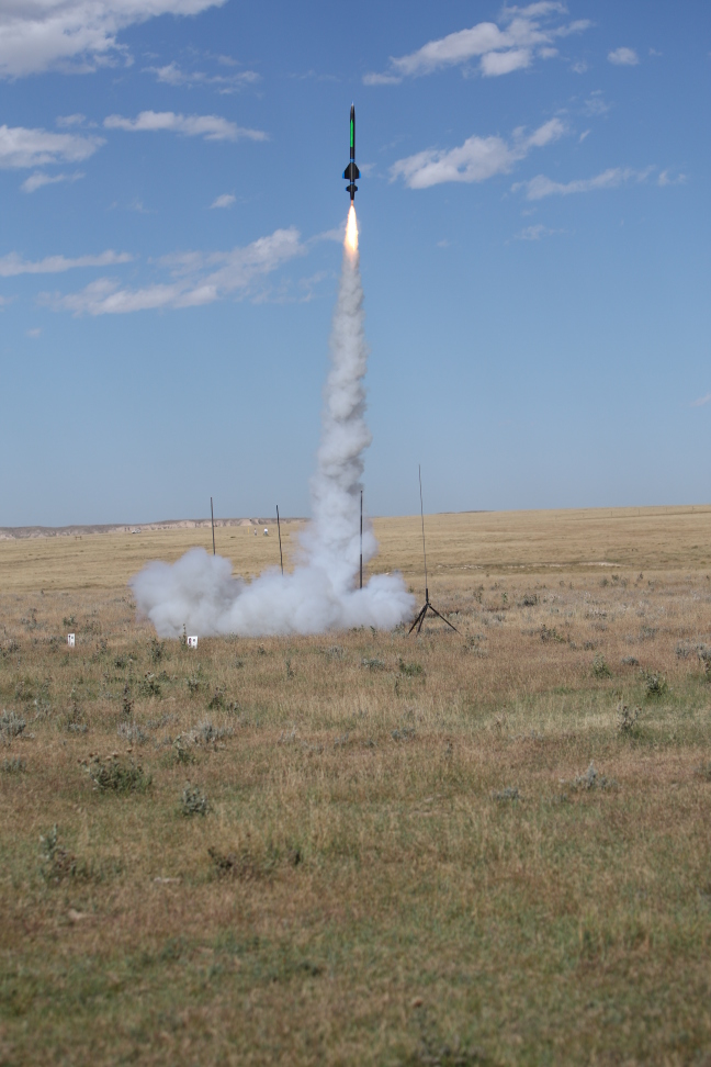
Pics from classmates:
This first one is from a student in our class who was able to go on a NASA zero-g flight (in which they fly a plane in parabolic trajectories that give effective weightlessness for extended periods. Looks like a ton of fun, I'm jealous!
And, from another classmate this term: I want to show you how I apply my physics knowledge outside of the classroom so I attached pictures of a rocket that I built and launched two weeks ago on the Wyoming-Colorado Border. The first picture is me with my 7 foot tall 10 pound rocket that I built sitting on the launch pad. The second picture was taken moments later and captures the rocket screaming into the sky sitting on top of a 5 foot long flame. The rocket engine used in this picture has a total impulse of 665 Newton-Seconds which propelled the rocket to over 2200 ft while attaining a maximum velocity of 262 miles per hour. This was the first time I launched this rocket and this was the smallest rocket engine that will fit inside. I plan on launching it early next month to an altitude of 4000 ft with a rocket engine that has a a total impulse of 1150 NS.
Last minute question about CAPA #8, for you late owls:
I don't know what you can do about it if anything but
for the first CAPA question will not accept the
correct answer (I do believe i have the right answer).
I have checked with many people who have gotten it
right and i have the same answers.
I appreciate your confidence on this, but
as far as I can tell CAPA's got the right answer on this one (as usual!) When you email me with CAPA questions, it's of course always much easier for me (and far more helpful) if you talk me through your logic and reasoning - that helps me figure out what you're thinking about and where you're going wrong... and might help you spot your own problem!
The trickiest question (in my opinion) for that first CAPA on set 8 is the one asking about what happens to the current through R4 when R3 decreases. You have to FIRST think about what R3 decreasing does to the current coming from the battery (which at this point should be a pretty familiar exercise for you?) But then, you have to think about what THAT does to ALL the various Delta V's around the circuit, bearing in mind that in the end the sum of all the Delta V's across the 3 "bunches" of resistors has to add up to the battery voltage, which is fixed. If you go through that, I'm sure you will find your mistake.
Good luck,
Question about CAPA concepts:
I had some trouble with problem #1 from the CAPA (#8) this week regarding what happens to current/power through one component if the resistance/voltage of another component is changed. I've submitted the correct answer with the help of fellow students but some of the answers were counter-intuitive and quite contrary to what I had reasoned. Each situation I had apparently misunderstood regarded altering the resistance of a resistor in parallel and then determining what would happen to the current through another resistor down the line, not in parallel with the altered resistor. I'll describe my reasoning, which led me to the wrong answers and hopefully you can see where I went wrong. I'll be referring to the diagram for problem 1 so you'll have to have it handy. One of the questions is as follows: "If R1 increases, the current through R6__". The correct answer for this question was "decreases," which I don't understand. My reasoning is as follows: If the resistance of R1 is increased, the total resistance of the parallel resistor (R1 and R2 combined) decreases, so I reasoned the current through the equivalent resistor would increase (due to less total resistance) and thus current through the circuit as a whole increases, including the current through R6. Why is this not so? The person who helped me out said, "Just use Ohm's law: if resistance increases, current decreases. Simple as that." This seems oversimplified! It seems you must consider that the resistor is in parallel as I did and thus reason total current increases through the equivalent resistor. This seems like a rather key issue so if I don't get this straight I'll be in bad shape for the remainder of the course.
This will be much easier in person (!) but let me try to help:
My reasoning is as follows: If the resistance of R1 is increased, the total resistance of the parallel resistor (R1 and R2 combined) decreases,
So that's indeed the basic flaw in the reasoning. (If it was correct, the REST of your reasoning is all good!!).
But it's really true that increasing R1 INCREASES that parallel combination. You seem to feel that since adding an R in parallel lowers the effective resistance, then INCREASING an existing R in parallel must also lower the effective resistance. But that's not so. I'm trying to think of ways to help you visualize it, there are a few here:
Consider the very simple but extreme example of two parallel resisters, R and R. They have a combined total resistance of R/2, right? Now, let's INCREASE R1. Let's go all the way, make it go to infinity. So you have an INFINITE resistor in parallel with a regular old R. So what's the effective resistance of that pair? You need to convince yourself that it is just R. (The infinite side is like a broken wire now, it might as well not be there. As R1 gets bigger and bigger, less and less current goes through it, and the combination looks more and more like a single R) So look: adding resistance to R1 made our effective total go from R/2 UP to R! Increasing R1 INCREASES the resistance of the parallal pair.
Go the other way. DECREASING R1 all the way to zero - you would have an ideal zero-R wire in parallel to an R. That looks like a 0 resistance situation to current, it ignores the R and goes through the zero path. So here, decreasing R1 has decreased the effective resistance.
Mathematically, Reff = 1/(1/R1 + 1/R2). If you start increasing R1, the first term in the denominator (1/R1) is getting SMALLER, and a smaller overall denominator means a bigger answer. That tells you that increasing R1 increases Reff.
I don't know if the math, or the extremes, are helping. Maybe just try a few concrete examples? (Try plugging in R in parallel with R, then try 2 R in parallel with R, and see that the effective result has gone UP)
To me, It makes sense that ADDING resistance anywhere in an existing circuit is just making it harder for current to flow through existing paths. It's not like you're opening up a NEW parallel path, you're making an existing one harder to go through! But I sympathize that this seems a little simplistic..
So now I'm trying to get back to the heart of your basic idea - you seem to be puzzled about how: if adding an R in parallel LOWERS R(eff), why does INCREASING R in parallel RAISE R(eff). I've been thinking about that, and I think I've got it. Let's start with a single wire, of resistance R. I would claim that that's equivalent to that R in parallel to a broken wire. (After all, a broken wire, which is an infinite R, in parallel doesn't do a darn thing, since nothing goes through it!) So any individual R is REALLY like an R in parallel with like this "virtual" infinite second R. So when you "add" a new resistor in parallel to your first one, what are you doing? You are not really adding an R.... you are actually REDUCING that infinite parallel R DOWN to the new chosen value of the parallel guy. Reducing the "virtual" parallel, infinite resistor DOWN to the new parallel R is what reduces the overall resistance R(eff).
OK, that's me, making sense of this for myself! But of course, you have to do it your own way! Maybe this helps, but if not, feel free to come by some time, we'll get it for you! (And yes, I agree, it's pretty key, you can bet this will show up on the next midterm in some guise!)
Thanks for continuing to work and think about it, very cool! I'll talk to you Monday!
Practice Exam questions:
Hello- I just finished the practice test that you posted and I had a few questions. I
undrestand that this is late notice and that you may not have time to respond to
this.
1. In number 13 it is asking a question that involves dielectric constant.
Someone in class said that you said this would not be covered on the test, but I
just wanted to check.
2. In number 16 it says "12V, 500 cold cranking amps". What exactly does this
mean? Im pretty sure you use the equation Ne=i(change in t) but I am confused
if I use the 12V to solve for current, or if i use the "500 cold cranking amps" in
the eqation.
3. In number 17, I found the correct equation but don't know how to determind
if it is to the right or to the left.
4. Lastly, in number 9, I am lost. Any explanation for this problem would be
great.
Thanks so much if you have time to answer any or all of these questions.
No dielectrics on this exam, indeed.
500 cold cranking amps just tells you the MOST current the battery can put out.
In #17: well, does current generally flow from high voltage to low, or vice versa?
In #9: Maybe revisit pp. 921 and 922 of your text? (Or, page "29&30"-12 of my lecture notes?) The story of finding V from a continuous distribution of charges is a lot like finding E from such a distribution ( look at the first midterm, we had a question similar to this one for dE) The two big differences are that V is not a vector (so, no need to take any x or y components!) and dV = kdQ/r, rather than dE = kdQ/r^2 (watch out for that denominator)
Hope this helps! Sorry if it's a litle brief - I'm in a bit of a lousy shape right now - came down with some sort of food poisoning this afternoon, ack, no fun! But, I'm feeling better, hoping I'll be back in good shape for tomorrow!
See you tomorrow
Steve
Quick question about current:
Professor, I know and understand that when a current reaches a junction, the sum of the two currents leaving the junction must equal the current going into the junction (in steady-state). i.e. I1 = I2 + I3.
Here's the question: Can we assume that the current splits EQUALLY into each wire leaving the junction (that is, I2 = I3)?
Thanks.
Good question. Answer is - definitely not! It will totally depend on what is further down the wire. You have to take a step back and look at the bigger picture to decide how much current will choose to go into wire 2, and how much into wire 3. (Imagine if there is a very LARGE resistance further down wire 2. Then much less current will go that way) The only time the current will split equally into the two paths is if the resistance of both of those paths is equal.
If you want a concrete example, check out e.g. Ex 31.11 in your text (and compare I1, I2, and I3. They are not equal, but on the other hand, they DO still all add up to exactly I(battery)! (which is Kirchhoff's junction rule)
And a followup question to the above: Just trying to understand: Could I think of it as the current "looking ahead" down the circuit, so that more can take the path of least resistance (literally speaking)?
Yeah, sort of! Electrons can't literally look ahead, of course, but maybe its more like water flowing down a pipe - which would notice a difference as it enters a junction (like one pipe splitting into two pipes), if e.g. one path is narrower (high resistance) and the other path is wider (low resistance). Clearly SOME water will flow through both output tubes, but MORE will go through the path of lower resistance.
This would still be true even if the two output pipes looked the same *locally* (right there at the junction), if one of the two pipes necked down further along the way, and the other did not, then less water would flow through the narrower (more resistive) one... The water would "know" because information about trying to squeeze too much water into a given pipe would transmit itself VERY fast back down the pipe if you ever tried! (In the case of our circuits, there would be a speed-of-light communication that there is a resistor "down the pike".
Remember that all wires are FULL of electrons at all times. So if we send in some current on one end, it's like putting one extra drop in one end of an already-full tube: another drop will pop out the far end nearly instantly. It's not *literally* the same drop, but it still looks like "conservation of current": one drop in, one drop out the other end! This water-in-the-pipe metaphor is not perfect, but it's not bad... Not sure if it helps - some people like it, some don't find it useful.
Glad you're puzzling over this - keep thinking, and keep asking me questions 'till you feel like it makes sense! One thing I'd recommend is going to phet.colorado.edu, and fire up the CCK (Circuit Construction Kit). You can make a simple circuit very easily, and it shows you the flow of electrons, you might find it all gets clearer if you set up a parallel circuit (so one wire leaves a battery, then SPLITS, goes through two different resistors, then recombines and goes back to the battery) As you vary one of two resistors, just watch the currents adjust! It can be pretty helpful.
See you in class tomorrow,
Steve
Question about concept test explanations:
Hello Professor,
I checked online for the clicker concept tests as you had recommended when we met with you during office hours, but I realized that the posted concept tests do not have the answers with them. Where would I find the answers to the concept tests, or do I need to come in for office hours?Thank You,
Did you go to the "Lecture Notes, Concept Tests and More" link, and then click on "Concept Tests"? On that page, I have *two* links for each chapter: first, just questions only, and then (after we're done with the chapter), question with answers. (These are all pdf files. Some are rather large, you'll want to do this on a machine with a decent internet connection)
Is any one of those links failing, or are you just not finding the link at all? Let me know, there should be solutions up now for all concept questions through (and including) the voltage and capacitors material.
Also at the bottom of that page is a link to the daily "histograms" (where you can see the in-class votes again, and also, if you look at the table associated with each plot, what the right answer is!)
Cheers,
Steve P.
Question about E and V:
Is there ever a case where E and V can both be zero? Or does it depend on where you set zero to be? It kind of seems like you always have at least one or the other.
E and V are rather different things, so both CAN be zero, or one can be and the other not... you can create just about any configuration you like!! As far as V is concerned, there is this additional issue that you can always set any ONE point to be called zero (you can only pick one point though, all other points are then determined by the physics!) But even if you decide to follow the canonical "V=0 at infinity", I think I can build charge configurations that give just about any interesting combination of E and V at various points in space that I like.
Consider these examples:
If I choose the center of the earth to be V=0, then we have E=0 and V=0 at the same place (namely, everywhere inside the earth. E=0 because it's a big conductor, and V=0 because if E=0 there is no DIFFERENCE in voltage between different points, so if it's zero at one place, it's zero at all places within that conductor). But the value of V is arbitrary, I could also have set it to be zero somewhere else, in which case it would be non-zero (but still constant) everywhere in the earth. So I don't think this example satisfies what you were puzzling about in your question.
If you decide to call V=0 out at infinity, then I'm thinking about your question of whether you could find a point with E=0 AND V=0. Our two class examples of a pair of charges (+ and +, or + and -) did not work, at least not at the midpoint. (In the first case E=0 but V is not, in the second case E is not, but V=0). But I think you can do it with MORE than two charges. In fact, I think there was a CAPA problem due yesterday with FOUR charges, two plus and two minus, and right at the center between them all, we had E=0, because we had two +'s on the "diagonal", and two -'s on the other "diagonal", so the E's canceled out pairwise. But because it was all symmetric with zero net charge, we also had V=0 at the midpoint. So there was a case with E=0, V=0, and V=0 out at infinity, and yet nothing is "trivial", and at different points you get all sorts of different possibilities for E and V being zero and nonzero!0
This help?
Cheers,
Steve
Connecting this class to the Physics of Black Holes
About the slides you showed today in lecture of potential energy of two negative charges along the distances 0 to infinity (formed a hyperbola), does the potential energy level off near zero so that two electrons could touch or can two electrons never touch? The reason I ask is because one or the other would have to be true in order for the KE to not be infinity whereby velocity would exceed the speed of light (I'm also takes ASTR2030-Black Holes)
Are you talking about the graph that showed a "1/r" curve, (that is high near the origin and heads off towards 0 at infinity? Or are you thinking of another slide?) That graph is technically not a hyperbola, it's just "1/r", but they do look similar. So, your question: can 2 electrons ever touch? The simple answer is no... First of all, the "electron" we're talking about (in 1120) is of course a model, it is a mathematical abstraction used to describe physical objects and predict their behaviour. Electrons can interact, and the more energy they have to start with, the more strongly they interact (the "closer" they get). But you will never have two electrons in the same exact place at the same time, which is what you might mean by "touching". It would require infinite energy, which we don't have at our disposal! We're studying classical physics here (it's still pre-quantum) In this model, electrons are points, with no dimension or spatial extent, and thus the potential energy goes to infinity as they approach closer and closer. Quantum mechanically, the electron must be represented by a "wave function", which you might think of, in a very loose way, as "smearing out" the particle. It's not a physical smearing, it's more a statement that you cannot know with absolute certainty where an electron is (and how fast it's moving) So in fact it is not completely meaningful to talk about two electrons "touching". (But even in quantum mechanics, *most* of what we are saying in Phys 1120 carries over.)
Going the other way, when you have a + charge and - charge, the graph is turned upside down, and then it might look like particles, released initially from rest, would keep getting closer and closer, going faster and faster, leading to some paradox? This seems to be the issue you're worried about in your comment - that the increasing KE would at some point mean v>speed of light. So first of all, note that KE can go to infinity (or at least, very high) without v *ever* exceeding c. That arises from a modification of the old non-relativistic formula (KE = 1/2 mv^2 is ONLY true if v<<c, you cannot continue to use that formula when objects are moving close to the speed of light, you need to make relativistic corrections) Since 1120 is still classical, we're not going to worry about relativistic corrections, we'll save that for Phys 2130! But you're right, they're there, and I'm kind of just sweeping them under the rug. In the end, two oppositely charge particles will also never "touch", again due to quantum mechanics - their interaction will not follow the simple Coulomb formula because you cannot really think of objects as "pointlike" in this simple way when you get down to subatomic distance scales...
Hope this helps, happy to chat some more if you want to connect this class to your Black Holes class!
Cheers,
Steve
Physics of Lightning
Dear Professor Pollock,
Hi, I'm from 1120, and as I was studying for the test, I was reading over your online notes. The part about lightning intrigued me; is it possible that the positive charges tend to rise to the top of the cloud and negatives sink simply because the negatives have the extra electrons and there for are 'heavier'? Or is the real world never that simple? Is there any way to test something like this? I can understand the cloud causing dipoles on the earth, and ultimately creating cloud-to-ground lightning, but it seems like within a cloud things would want to even out before it builds up enormous amounts of potential. I appreciate any thoughts.
Thanks,
Glad to hear from someone reading the optional part of my lecture notes :-) I thought the lightning stuff was cool too. But I really don't have a good explanation for why the -'s tend to be at the bottom of the thundercloud. I don't know if the negative part of the cloud is negative because it's negative ions (thus, heavier), or just loose electrons (thus much lighter), but even if it were ions, the extra weight of an electron is SO tiny, a small fraction of a percent of the mass of an atom, that I can't imagine that could be the driving effect in why things separate vertically. There is a lot of convection and turbulence in a storm cloud, lots of material objects (like water molecules) getting moved around by strong thermal currents past other material objects (like air molecules), so there is certainly lots of possibility for energetic "rubbing", which tends to charge things up as we've seen!
I really only read a little about this in Feynman's lectures (he wrote a very wonderful freshman physics textbook which is pretty darn impressive!) , and some online notes, but it seemed to me with my brief study of this that people don't fully understand the physical mechanisms involved. Maybe it's something ripe for an up and coming atmospheric scientist to figure out! (Or maybe I just didn't dig hard enough...) If you happen to learn more, pass it along to me!
Cheers,
Steve P
CAPA Set #4 question
Hi, I was trying to finish my CAPA this evening however I have been having some trouble on Number 4. It asks for the magnitude of the electric field at a point 1.3 cm from the center of a sphere with radius 2.3 cm and a charge of 7.6E-9 coulombs.
In the book I located example 27.4 on page 867 which is the same problem. I used the equation that is given there and plugged in the numbers that capa gave me. However it said it was the wrong answer so I re-input my numbers but I got the same thing as before. The equation that I use was E_inside= K*((Q*r)/(R^3)), if this isn't the right one I would love for some help in finding the equation that will help me to get the correct answer.
Thank you for your time,
There is a very important difference between CAPA #4 and the example on p. 867, namely - p. 867 is all about a *uniformly charged* insulating sphere. But this CAPA problem is for a *conducting sphere* (metal, rather than plastic, say). Think about the physical difference! (It's what we focused on in Wed's lecture) - in a conductor, where does any excess charge sit? And, what is the E-field *everywhere* inside the conducting sphere, in equilibrium? (In the example problem, it is uniformly charged, which means that there are unbalanced +Q's "smeared out" uniformly everywhere throughout the sphere. But in the CAPA problem, it's a conductor, so the charges distribute themselves totally differently.)
Does that help you get going? Let me know if you're still puzzling about it! (I think you'll find the CAPA problem considerably *easier* than the example from the book, once you think about the physics here! )
Cheers,
Steve P.
A question about the online pretest:
Hello Steven
I tried to take the pre test today, but the web site wouldn't let me.
Do i need to do something special.
Thank you
Pretest schedule runs from just after my 2nd lecture on Friday (i.e. 1 PM) until just before the *first* Tutorial on Tuesday (i.e. 8 AM). So, it's basically a weekend activity (or Friday afternoon, or any time Monday...) Any other times and it'll just yield a web error message. Having it up much earlier is usually kind of premature, the point is for people to be thinking about the material for the upcoming Tutorial "just in time", so it'll be fresher in your mind on Tuesday. (Plus, if you do it too early, before we've covered it in lecture, then it's not really so helpful.) Think of the pretest as like a bridge between lecture and the Tutorial!
Hope this makes sense...
Cheers,
Steve P.
A question about motion of charge:
Hello Professor Pollock,
I had a quick question that my mind is having trouble understanding. My question boils down to how a positive charge or whatever we call the charge of a proton can actually travel a distance. ...my mind has trouble visualizing how a positive charge moves.
In chemistry you learn that electrons can relocate to a more stable atom or in our case be rubbed off. But for a proton (the positive charge) it cannot easily escape the nucleus.
All I can really come up with is that the protons or atoms never actually move but the ratio of electrons to protons just changes to where there is a net positive charge(polarization sort of).
...Thanks for the help and I will ask my TA next week if you do not have time to respond. Thanks again Prof. Pollock, have a good one and I'll see you in class sometime.
I *think* you're basically on the right track. The protons are (generally, not always) fixed in a lattice, so yes, it's just the negative electrons which are mobile. Much of what you said seems right (though you're using words a little differently than I might, so I'm just not 100% sure what your picture is) I'm going to show a pictorial model in class Friday that *might* help a little (?), in which I'll draw a lattice of "+"'s which are fixed, and on top of them a second lattice of "-"'s. If you slide the lattice of "-"'s a little, what it LOOKS like is as though minus and pluses are both moving. It's a cool trick: in general, a negative moving to the left is *equivalent* in almost every respect to a positive moving the same amount to the right. You can't tell the difference from a macroscopic perspective.
Think of it this way. Imagine two atoms side by side, #1 on the left, #2 on the right. Say #1 is ionized (meaning it lost an electron), so it has net charge +e. (Right? It was neutral, then it LOST a NEGATIVE charge, which leaves it positive) Some people would say this atom has a "hole" (a missing electron, a SPOT where an electron could fit). So in a sense, you could say that holes look positive...It's just a novel way of thinking of things - this atom "has" a hole which looks like a positive entity! Now say #2 is neutral. Next imagine an electron hops from #2 to #1 (filling in the "hole") So from the outside, squinting your eyes a little, you could EITHER say what I just said (negative charge moved left from #2 to #1, leaving behind a hole in #2 where that electron just was), but you could ALSO say, no, a positive hole hopped RIGHT from #1 to #2. It left #1, so that one no long has a hole (so it's neutral) but the hole hopped to the right, so #2 now has a hole. Either way you think of it (electron moving left, or hole moving right), atom #1 is now neutral, and #2 is now positive. What moved, a negative to the left, or a positive (hole) to the right? Well... it was the electron that moved, but it's just fine to THINK of it as a positive entity moving to the right. Note that this entity is not a proton (it's not massive, it's not stuck in the nucleus!). It's a "hole". It's not an anti-electron, but it sort of acts like one... We can think of that as a sort of "quasi-particle" which can roam around from atom to atom.
So in this way, we can TALK about negatives moving left, or positives moving right, it's really all the same, and it doesn't matter how you choose to think about it - the end result is basically the same!
Not sure if this helps, keep on thinking about it, and feel free to visit me after class or office hours so we can chat some more, if you like.
Cheers,
Steve P.
You can see all the old "virtual office hour" questions from this whole semester here